How EDSFF is Making NVMe® Technology Even Cooler
BlogBy Mike Scriber, Sr. Director, Server Solution Management, SuperMicro
With data center operators’ requirements for faster access to massive amounts of data than ever before, the choice of storage technologies and associated infrastructure has become a critical consideration when IT departments design and implement their next-generation data centers. As storage technologies continue to increase in both performance and capacity, some decisions need to be made to deliver fast results to enterprise customers.
Persistent storage is moving quickly from spinning disk drives (HDDs) to solid-state disks (SSDs). The advantages of using SSDs and other storage devices, with no moving parts—which are prone to failure— are that SSDs have lower latencies and lower operating expenses (OPEX). SSDs in the U.2 form factor are a familiar form factor for many computing environments, where density and the associated costs are not a priority. However, when higher density storage is required, several factors should be considered when deciding on local flash or an all-flash array.
A new form factor for SSDs was recently created, the Enterprise & Data Center SSD Form Factor, more commonly known as EDSFF. The EDSFF specifications were created by 15 companies, working to standardize and optimize NVM Express® (NVMe®) SSD hardware. This includes not just the physical form factor but the connections to the PCIe bus as well. The EDSFF connector only supports PCIe signals, so this connector can only work with NVMe SSDs. It will not work with SAS or SATA drives. Standardization is crucial for a more rapid adoption of this new storage technology, enabling storage vendors to seamlessly work with systems suppliers and deliver high-performing products to end-users.
One significant advantage of the EDSFF drive is the improved cooling for the entire system. Using the U.2 (2.5″) form factor requires a vertical backplane in the front of the chassis, which blocks the airflow to the back of the chassis, where the CPU and memory are located. The backplane has cutouts to help move air through the chassis, but there is still an air dam restriction. The key with EDSFF is that the EDSFF backplane is placed down flat and doesn’t block the airflow, which results in more efficient cooling of the SSDs.
This design leads to a simpler chassis, less costly fans, less power draw, and less cabling, which reduces costs. There are some additional complexities and costs associated with using a U.2 form factor, including, but not limited to:
- Backplane cutouts
- Additional cables
- Drive cages
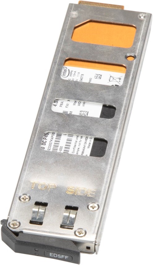
Figure 1 – An EDSFF Form Factor. Image courtesy of Super Micro Computer, Inc.
The EDSFF is designed to reduce the need for:
- Powerful fans
- Internal cabling
- Vertical Backplanes
Figure 2 shows a typical chassis that contains several EDSFF SSDs. The airflow is not blocked by the backplane and can flow right over the drives.
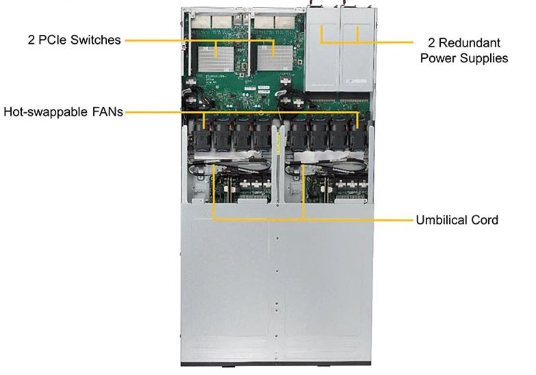
Figure 2 – Image courtesy of Super Micro Computer, Inc.
With the new EDSFF products, airflow, measured in cubic feet per minute (CFM), increases over the SSDs and is improved because there are no physical restrictions. Figure 3 (courtesy of Intel) shows the thermal signature of a U.2 form factor SSD compared with an EDSFF SSD. The graph shows up to 55% reduced cooling needed for an EDSFF SSD compared to a U.2 SSD at various CMF/drive.
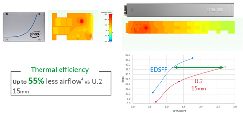
Figure 3 – Thermal comparisons of U.2 and EDSFF SSDs.
Another advantage of EDSFF drives is the connector. The EDSFF connector was designed for future high speed interfaces and is ready to support PCIe 5.0 and PCIe 6.0 architectures. Additionally, as the EDSFF specification has evolved, different form factors have been specified to fit various use cases. The EDSFF family includes both E1.S and E1.L form factors, as well as the E3 form factor. E1.L was developed to maximize capacity per drive and per rack unit in a 1U server storage array (JBOD, JBOF), with options for x4 or x8 lanes of PCIe technology, while fitting vertically in a 1U chassis. This form factor is optimized for high-capacity and dense storage use cases, offering improved data center TCO with storage consolidation and increased power efficiency.
The E1.S is a small form factor that fits vertically in a 1U chassis, designed wider than an M.2 to accommodate more media (NAND) packages for increased capacity per drive. E1.S offers improved flexibility for power, performance, scalability, and thermal efficiency, and is often used in Cloud compute servers and OEM 1U performance servers. Finally, E3 form factor was also designed as a new form factor alternative to U.2 and supports both 2U and 1U servers, fitting vertically into a 2U server and horizontally into a 1U server.
While the E1.S and E1.L are optimized for cloud and hyperscale data centers (due to them being standardized on 1U server form factors) the E3 is intended for use in standard enterprise servers (80% 2U, 20% 1U). E3 helps OEMs better support PCIe 5.0 architecture (with optimal signal integrity) while avoiding huge overheads in infrastructure cost due to lower base system infrastructure. E3 also includes support for future device types, such as SCM (Optane), AI, and accelerators, and offers more front serviceable IO slots to continue the scaling of PCIe IO from the CPU.
For a more in-depth discussion of the different form factors, visit the SNIA.org website.
In summary, the EDSFF SSDs will become increasingly important when choosing a system for demanding I/O needs. Understanding the new choices and the costs involved will lead to a more optimized selection for various workloads.