Technology Power Features
Technology FeaturesNVMe™ Technology Power Management Features
NVM Express (NVMe) architecture contains various features to manage the power of SSDs. In the data center, this can be used to throttle an SSD to a specific TDP (thermal design power) to manage platform thermals and total power draw. Max power is usually defined by a given form factor (e.g. U.2, M.2, EDSFF) but a drive can use NVMe specification features to change an active power state. This may be useful if a host knows it wants to write a considerable amount of data at once by giving a drive max power and performance. It can also useful for improving data center TCO by reducing the max active power of the SSD, which reduces SSD performance, but can be tuned by workload to achieve an optimal TCO.
Non-operational power states are mainly used in consumer/client SSDs to improve battery life. While the drive is idle, the drive can be at a near zero or zero idle power state, and NVMe architecture takes advantage of PCIe low power states to help achieve this. In mainstream client/consumer use cases, the SSD is idle most of the time, so low power features are incredibly important for improving battery life. These features are not widely used in data centers due to the latency tradeoff of PCIe L1 substates. However, we may see a reemergence of these features in less frequently accessed data center drives that are turned for warm or cold storage, where a lower idle power can help improve operational expenses from power. Typical data center SSDs today are intended to have a high duty cycle or percentage of the time the data is being accessed.
What are Active Power States?
In NVMe architecture, the Active Power (ACTP) indicates the largest average power the NVM subsystem over a ten second window. Each controller in a subsystem can support up to 32 power states. If a controller supports Autonomous Power State transition, the host can automatically transition between supported power states to meet thermal requirements.
Supported Power Features Via the Identify Command
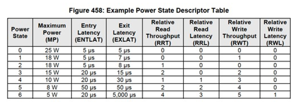
Within this identify command, users can view the number of power states a controller supports along with the details of each power state. If the controller supports Autonomous Power State transition (apsta), the value will be set to 1.
An overview of NVMe technology power management can be found in section 8.4 of the latest NVMe specification.
Static & Dynamic Power Management
The power management capability allows the host to manage NVM subsystem power statically or dynamically. Static power management consists of the host determining the maximum power that may be allocated to an NVM subsystem and setting the NVM Express power state to one that consumes this amount of power or less. Dynamic power management is illustrated in Figure 1 and consists of the host modifying the NVM Express power state to best satisfy changing power and performance objectives. This power management mechanism is meant to complement and not replace autonomous power management or thermal management performed by a controller.
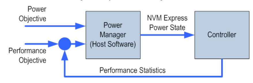
Figure 1: Dynamic Power Management
Changing Device Max Power (MP)
SSD power scales with the capacity of the drive (the number of NAND dice increasing) and the SSD controller (large die size to increase performance comes at additional power). For a specific capacity, the active power states can be tuned for common operational power modes for data center servers. Many drives today do not fill out the latency or relative throughput, since they may have to be measured on every firmware version. However, being able to instantly send a command to the drive to throttle the SSD max power is very useful. In some server use cases that have 24 or more NVMe SSDs in a single server, the optimal platform configuration may be to throttle the max power of all the SSDs. This helps achieve better overall platform level capacity, power and performance by adding additional drives.
Figure 2 is an example of an enterprise NVMe SSD with three operational power stats, at 15W, 20W and 25W.
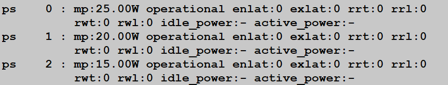
Figure 2: Example output from the Intel® SSD D7-P5500 Series
To change active power state via nvme-cli, users must is issue the following:Copy to Clipboard1
nvme set-feature /dev/nvme0n1 --feature-id=2 --value=1 or --value=2
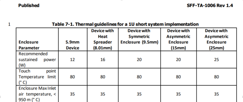
Figure 3: EDSFF recommended power & thermal guidelines, Source: SNIA SFF-TA-1006 Rev 1.4
Figure 3 is an example of the EDSFF specification from SNIA SFF, which includes different maximum power levels for different thermal and enclosure options. An SSD vendor could support a single SSD design that can be used with multiple different thermal options and use the NVMe power states to limit the power upon a recommended form factor TDP.
Power Features for Desktops and Workstations Mapped to NVMe States
Desktops and workstations include power states, that are independent of NVMe architecture. During a system sleep, the NVMe SSDs are physically powered off, where fast resume and entry latency can be very useful. NVMe SSDs can enter into low idle power states even in platform S0, where the system may be active but the drive is idle. This is where the autonomous power states can be useful on the NVMe SSD.
Active Power States
S0 – Working State and modern Standby
S0 (Working State): Everything is in active state
S0-Low Power Idle (Modern Standby): System can be partially slept to save power on components that are not in use. The system can return to a fully working state quickly from this stage
S1, S2, S3 – Sleep
The system enters sleep mode based upon user and app activity
Volatile memory is kept refresh
S4 – Hibernate
The system is off but system state is saved and can be resumed later
The system responds to keyboard or other hardware inputs
S5 – Soft Off
The system is completely shut down
G3– Mechanical Off State
Need full reboot to bring the system back to action
No power is consumed in this state
For desktop computers, this is the state when the plug is removed from the socket
In Power Consumption: S0>S1>S2>S3>S4>S5>G3
Thermal Throttle Management
Host controlled thermal management provides a mechanism for the host to configure a controller to automatically transition between active power states or perform vendor specific thermal management actions to attempt to meet thermal management requirements specified by the host. This can be useful when taking an SSD used for either a desktop/workstation or laptop (M.2 NVMe SSD) and tuning it to its thermal environment. In an M.2 SSD in a desktop with a large heat sink, the user may want it to throttle at a higher temperature for optimal performance. If using the same drive in a laptop, the user may want to optimize for battery life and thermal performance so as not to heat the rest of the laptop. It is recommended that the user take advantage of NVMe thermal management features.
Thermal Throttling prevents overheating of components when it takes heavy workload. When the temperature is less than the specified threshold, file transfer speed across the PCIe technology link is increased for faster performance. On the other hand, if the temperature is higher, speed is slowed down.
Thermal Management Temp2 > Composite Temp > Thermal Management Temp 1: The controller should start transitioning to lower power active power states (that performs light throttling) or perform vendor specific thermal management actions. Additionally, the controller should minimize the impact on performance to reduce the Composite Temperature.
Composite Temp > Thermal Management Temp2: The controller should start transitioning to lower power active power states (that performs heavy throttling) or perform vendor specific thermal management actions regardless of the impact on performance in order to attempt to reduce the Composite Temperature.
Once, Composite Temp < Thermal Management Temp: The controller should return to the active power state that the controller was before entering a lower power active power state or stop performing vendor specific thermal management actions.
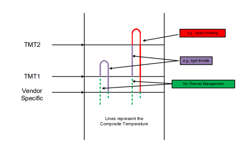
Figure 4: Thermal Throttling Management
Power Features for Laptops and Mobile Devices
With regards to laptop and mobile devices, power states and thermal management have shifted to extending battery life rather than optimizing performance. It is a common misconception that SATA devices are always lower power than NVMe SSDs. NVMe technology has many more advanced power features than SATA and achieves better performance while improving battery life. SATA SSDs generally do not have high performance controllers or consumer high amounts of power since they are limited to 550MB/s on the SATA 6Gbps interface. An NVMe SSD that can perform a workload faster, then go to a zero power idle state, can improve the power efficiency of a laptop.
Figure 5 is an example of mainstream M.2 NVMe SSD that supports both NVMe Autonomous power State Transition and PCIe Active State Power Management to balance performance with battery life. The controller will transition to lower power active power states when not in use to conserve battery life. Intel 665p consumes as low as 100mW when it is active. However, it is reduced to 40mW during Idle state power consumption is and is reduced to 4mW power consumption during L1.2 Sleep.
Figure 5: Intel 665p power states | Power (Active): as low as 100mW -> Idle: 40mW -> L1.2 Sleep: 4mW
How PCIe Low Power States and NVMe Technology Features Achieve Near Zero Power Idle Power
- L1.1 and L1.2 are aggressive low power states of PCIe specification
- Traditional L1 states allow the reference clock to be disabled on entry to L1, which was shown to consume too much power due to leakage.
- L1.1 allows the common-mode voltage to be maintained, while L1.2 allows all high-speed circuits to be turned off. Runtime D3 (RTD3) is when the main power is removed from the controller. NVMe technology supports RTD3 for zero power idle power.
- If the device supports APST, the device can decide when to enter a different active power state, and support runtime D3 (RD3) for zero power idle state and fast resume.
- In Runtime D3 (RTD3) main power is removed from the controller. Auxiliary power may or may not be provided. RTD3 is used for additional power savings when the controller is expected to be idle for some time.
Contributors: Jonmichael Hands, Dennis Worley Jr, Lakhveer Kaur – Intel